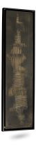


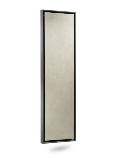


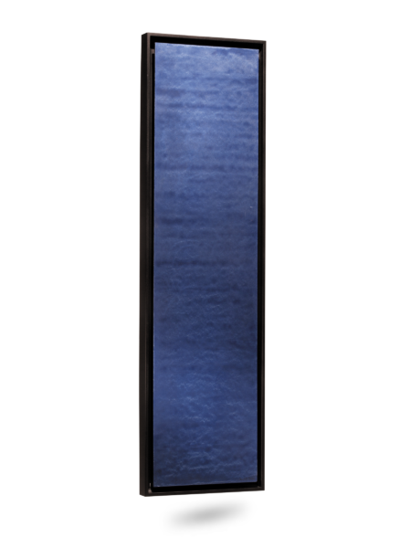
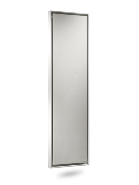
- S-03 Quartz grey
- S-03 Quartz grey
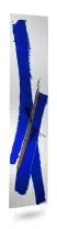
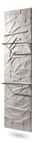
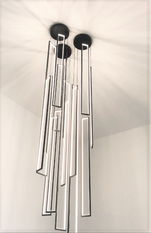
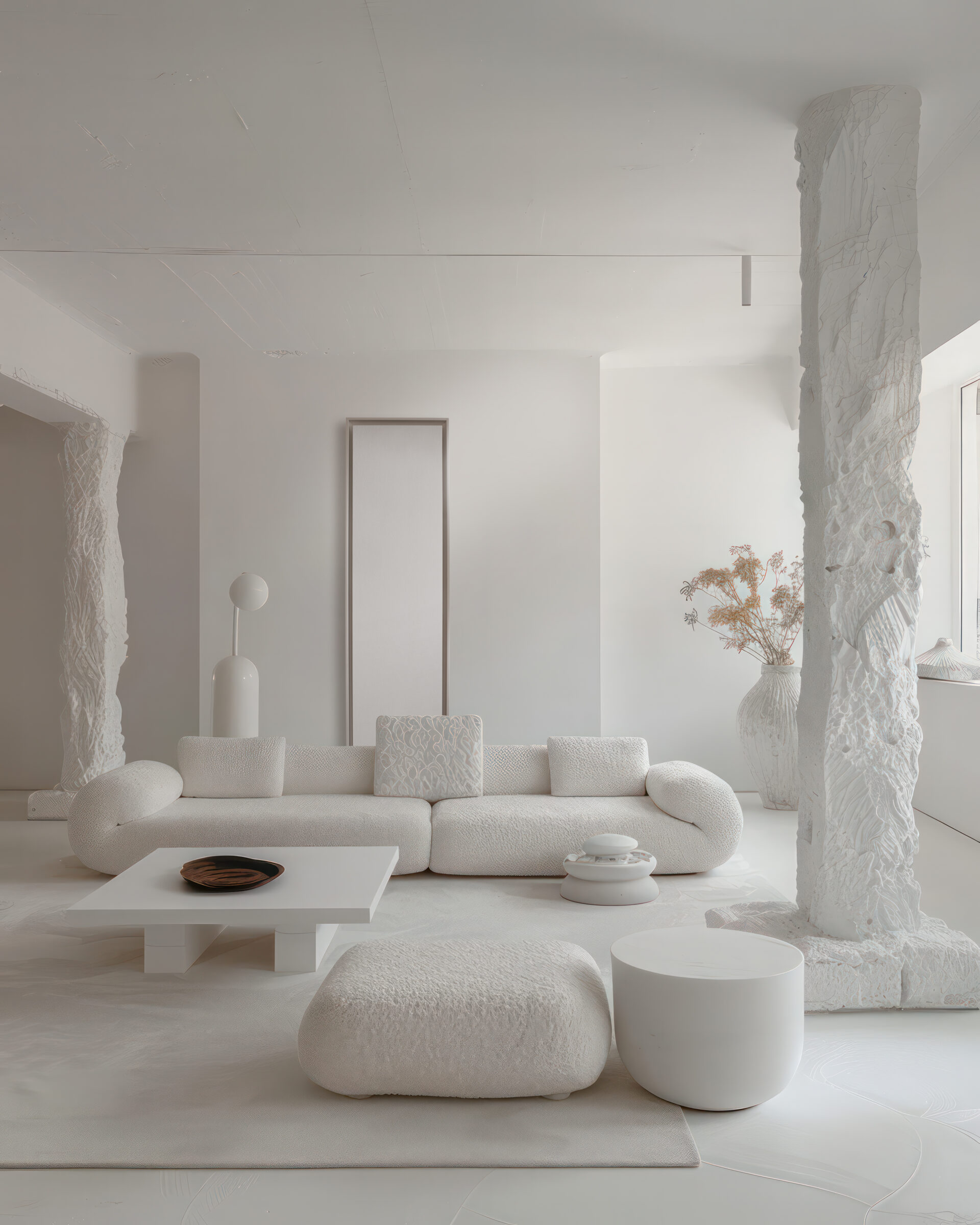
Minimalist aesthetics, CORE models can be patinated in Quartz Grey, Olycal White and other pigments on request.
GREENOR is a new generation architectural hydronic fan coil unit designed for visible installation in high-end residential and hospitality environments. Units operate on hydronic heating and cooling loops supplied by air-to-water heat pumps or central chilled water systems. Ultra-quiet, draft-free comfort for high-end residential and hospitality projects.
Delivering up to 10,000 BTU/h (3 kW) of cooling capacity per unit — CORE GREENOR connects to an air-to-water heat pump or a chilled-water network.

Ultra quiet
Draught-free and ultra-quiet for an exceptional climate
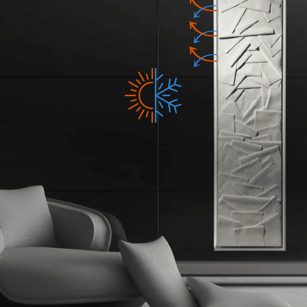
Heating/Cooling
Allows heating or air conditioning with Air/Water heat pump (chilled water technology) pump (chilled water technology).

Anti-viral exchanger / UV filter
Purifies air during a pandemic in less than 2 hours. Patented 100% copper vertical exchanger.
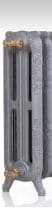
Greenor heating only
Works like a very high-power radiator (3740W) for existing boilers or air-water heat pumps
Greenor Reversible
Identical to the Greenor Heating only with air-conditioning option (1600W). Perfect comfort, very even & incredibly quiet
-
Submittal Sheet
General Description
GREENOR is a new generation architectural hydronic fan coil unit designed for visible
installation in high-end residential and hospitality environments. Units operate on
hydronic heating and cooling loops supplied by air-to-water heat pumps or central
chilled water systems. Ultra-quiet, draft-free comfort for high-end residential and
hospitality projects.
Key Features:
• Ultra-low air velocity (0.14–0.51 ft/s)
• Integrated 3-way control valve (24V)
• Low voltage internal components (24V) – Integrated UL-listed transformer
• Designed with UL / ETL recognized components
• Designed for low-temperature hydronic systems (heat pumps)
Applications:
• High-end residential
• Hospitality
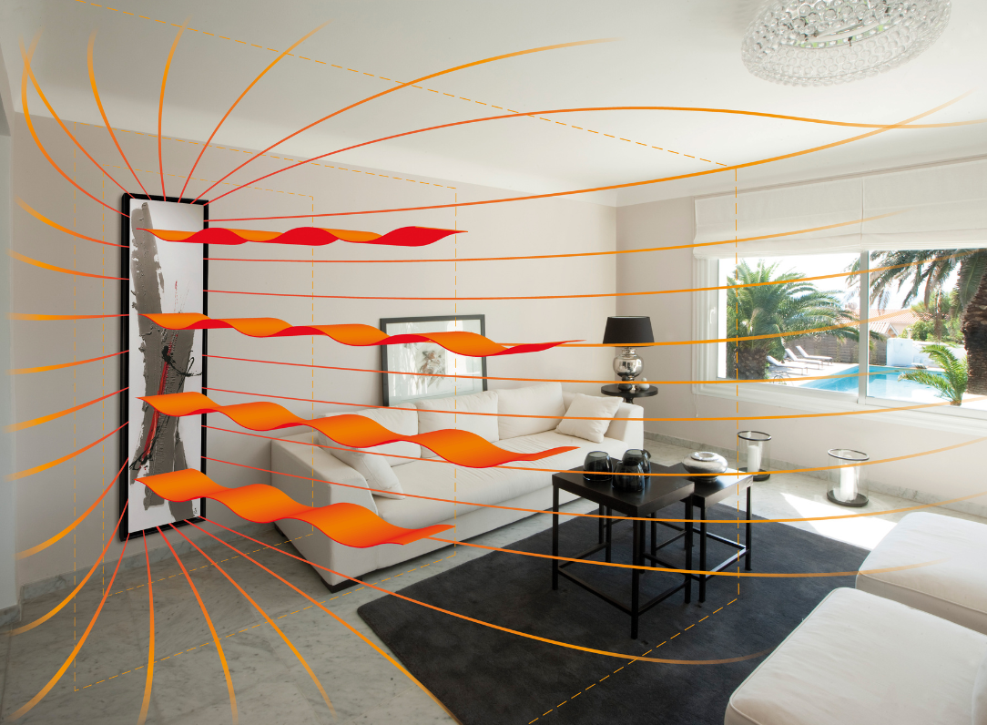
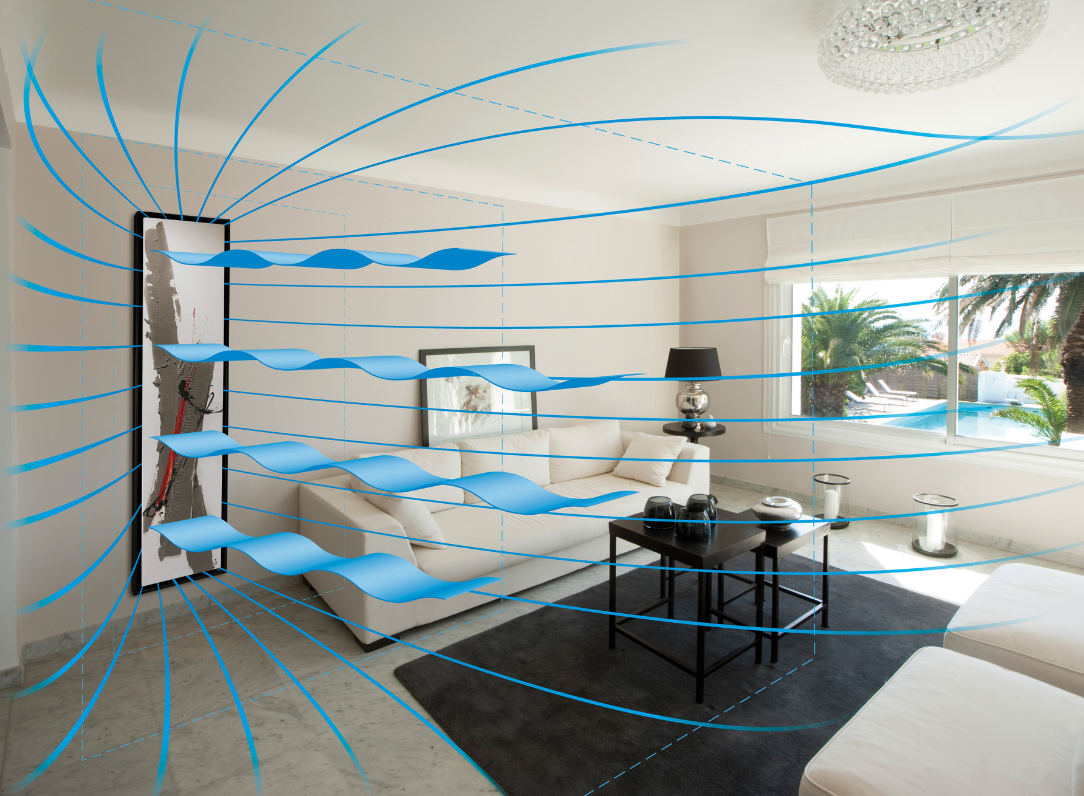
• Luxury apartmentsAirflow Concept & Comfort :
GREENOR units operate as free‑return hydronic terminals. Air is gently drawn through
the heat exchanger and discharged vertically along the front surface.
This creates a natural convection effect, ensuring smooth and homogeneous air
distribution throughout the room.
The low velocity avoids discomfort while maintaining effective heating and cooling
performance.
This ultra‑low velocity diffusion concept minimizes draft and improves acoustic comfort
Greenor :Hydronic Connections
• System Type: 2-pipe hydronic system
• Supply Connection: 1/2″ (or specify)
• Return Connection: 1/2″ (or specify)
• Factory-integrated 3-way control valve (24V)
• Recommended accessories: air vent, balancing valve, isolation valves
• Condensate drain connection (cooling mode): gravity drain or optional condensate
pump
Electrical Connections
• Power Supply: 120V / 60Hz (or project-specific)
• Internal transformer: 120V to 24V (UL listed)
• All internal components operate at 24V (fans, valve, controls)
• Low voltage thermostat connection (24V)
• Compatible with standard HVAC control systems
Notes
All connections to be performed by licensed professionals.
Refer to project specifications for final selection and installation details.
Consult CINIER engineering for custom configurations.Unit Dimensions & Clearances
Model Dimensions (W x D x H) Weight
GREENOR 21.25″ x 4.5″ x 74.8″ 127.8 lb
GREENOR XL 21.25″ x 5.8″ x 74.8″ 143.3 lb
Minimum Installation Clearances
Top: 4 in
Bottom: 4 in
Sides: 12 in (recommended for airflow)
Front: 12 in (recommended for airflow and service access)Condensate Management
Integrated condensate drain pan
Gravity drain connection
Optional condensate pump available
Condensed water volume : 0.18 gallon / hourCompliance
• Designed in accordance with UL / ETL safety standards
• Uses UL / ETL recognized components
• Electrical components selected in accordance with UL / CSA requirements
• Integrated UL-listed transformer
• Designed for integration into systems complying with ASHRAE comfort and HVAC
design guidelines
• Suitable for installation in accordance with IMC (International Mechanical Code)Heating Performance – Heat Pump Conditions (AHRI-style)
Entering Air: 70°F DB / 67°F WB
Entering Water: 120°F
Leaving Water: 100°F
Designed for modern low-temperature heating systems.
GREENOR Heating
Fan Speed CFM BTU/h GPM psi kPa dB(A)
Low 67 4196 1.19 0.13 0.90 14.8
Medium 114 7506 1.19 0.23 1.59 25.6
High 169 12761 1.19 0.46 3.17 35.7
GREENOR XL Heating
Fan Speed CFM BTU/h GPM psi kPa dB(A)
Low 171 7441 1.76 0.89 6.14 25.2
Medium 280 13590 1.76 1.66 11.45 36.3
High 339 23270 1.76 2.16 14.89 40.8Hydronic Data
Parameter GREENOR GREENOR XL
System Type 2-pipe hydronic loop 2-pipe hydronic loop
Typical Water
Flow ~1.2 GPM ~1.8 GPM
Pressure Drop 0.13 – 0.46 psi 0.89 – 2.16 psi
(0.9 – 3.2 kPa) (6.1 – 14.9 kPa)Cooling Performance (AHRI-style)
Entering Air: 80°F DB / 67°F WB
Entering Water: 45°F
Leaving Water: 55°FGREENOR
Fan Speed CFM BTU/h GPM psi kPa dB(A)
Low 67 2184 1.19 0.13 0.90 14.8
Medium 114 4094 1.19 0.23 1.59 25.6
High 169 5459 1.19 0.46 3.17 35.7GREENOR XL
Fan Speed CFM BTU/h GPM psi kPa dB(A)
Low 171 5050 1.76 0.89 6.14 25.2
Medium 280 6995 1.76 1.66 11.45 36.3
High 339 10277 1.76 2.16 14.89 40.8
Airflow values measured at nominal conditions.
Low airflow design optimized for ultra-quiet operation and architectural integration.Sound Level
Model Fan Speed Sound Level
GREENOR Low 14.8 dB(A)
GREENOR Medium 25.6 dB(A)
GREENOR High 35.7 dB(A)
GREENOR XL
Low
25.2 dB(A)
GREENOR XL Medium 36.3 dB(A)
GREENOR XL High 40.8 dB(A)
Sound data: according to ISO 11203, measured at 1.09 yd (1 m)Electrical Data
• 24V low-voltage internal components (fans, valves, controls)
• Integrated UL-listed transformer (110/240 V to 24 Volts)
• Integrated Honeywell 3‑way control valve with 24V actuator
• UL / ETL listed components (Intertek)
• Power Supply: 120V / 60Hz (or project-specific)Made in France
-
Basis of Design Specification
-
- Architectural Hydronic Fan Coil Units
Basis of Design Product: CINIER GREENOR Architectural Hydronic Fan Coil Unit.
The system shall provide ultra-low velocity air diffusion, silent operation suitable for
luxury residential spaces, and architectural visible installation.
The unit shall incorporate:
• Factory integrated Honeywell 3-way hydronic control valve (24V)
• Internal UL-listed transformer supplying all internal components
• Low voltage 24V electrical architecture
• Ultra-low air velocity diffusion system
• Ultra-quiet fan operation suitable for residential environments
• Compatibility with air-to-water heat pump hydronic systems
Equivalent products must demonstrate compliance with all architectural, acoustic, and
hydronic performance characteristics described in this specification - Greenor® is listed:
CE norms: EN 60335-2-30, EN 55014-1 (Ed 2006), EN 61000-3-2 (Ed2006) and EN 61000-3-3/A1 (Ed 1995/01): for the European markets.
UL 1995, issue:2011/10/14 Ed:4 UL Standard for Safety Heating and Cooling Equipment for the US market.
CSA C22.2 No. 236, issue:2011/10/14 Ed:4 Heating and Cooling Equipment for the Canadian market.- More information : FAQ Technologies Greenor
- Architectural Hydronic Fan Coil Units
-
-
Installation
Required 2 person or 1 person with the appropriate mounting tools.
Connection to be made by a professional (plumber HVAC specialist).
Connection center: 4 cm – Installation instructions on request.
Access to Components
• Front panel removable or security door for service access
• Direct access to:
– Fans
– Hydronic coil
– 3-way control valve (factory integrated)
– Electrical components (24V)
• Simplified internal layout for quick servicing
Hydronic System Maintenance
• Standard 2-pipe hydronic connections
• Integrated control valve reduces external components
• Compatible with standard HVAC maintenance proceduresService Benefits
• Reduced maintenance frequency
• Easy access without unit removal
• No complex disassembly
• Designed for residential and high-end applicationsEngineering Note
GREENOR units are engineered to minimize service interventions while maintaining
optimal performance. The combination of low airflow operation and simplified
component access ensures long-term operational reliability.Installation Guidelines
• Installation shall be performed by qualified professionals.
• Due to unit size and weight, handling by two installers is recommended.
• Wall structure must be verified for load-bearing capacity prior to installation.
• Ensure adequate clearances for airflow and service access.
• All hydronic and electrical connections must comply with local codes.
Unit must be installed in accordance with project specifications and local building codes.


You should also like

Add to a wishlist
Create a new list in order to add products.